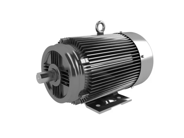
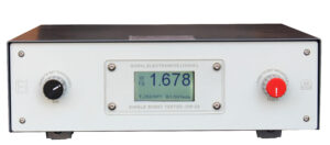
3 Phase Power Analyzer
It is widely used in Motor No Load Test & Blocked Rotor Test. It is also used to test watt loss of Motor. 3 Phase Power Analyzer is also used in Motor Test bench.
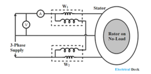
No Load Test- The no-load test of an induction motor is similar to the open-circuit test of a transformer. The motor is not connected from its load, and the rated voltage at the rated frequency is applied to the stator to run the motor without a load. The 2-wattmeter method measures the input power of the system.
When the motor is connected across the supply mains without load, it draws small current from the supply mains. This current will flow through the series field and armature, the speed tends to increase so that back emf may approach the applied voltage in magnitude.
Blocked Rotor Test- In block rotor test, the low voltage is applied so that the rotor does not rotate and its speed becomes zero and full load current passes through the stator winding. The slip is unity related to zero speed of rotor hence the load resistance becomes zero.
The induction motors are widely used in the industries and consume maximum power. To improve its performance characteristics certain tests have been designed like no-load test and block rotor test, etc. A blocked rotor test is normally performed on an induction motor to find out the leakage impedance.
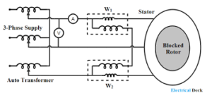
Apart from it, other parameters such as torque, motor, short-circuit current at normal voltage, and many more could be found from this test. Blocked rotor test is analogous to the short circuit test of transformer. Here shaft of the motor is clamped i.e. blocked so it cannot move and rotor winding is short circuited.
In slip ring motor rotor winding is short circuited through slip rings and in cage motors, rotors bars are permanently short circuited. The testing of the induction motor is a little bit complex as the resultant value of leakage impedance may get affected by rotor position, rotor frequency and by magnetic dispersion of the leakage flux path. These effects could be minimized by conducting a block rotor current test on squirrel-cage rotors.
In the blocked rotor test, it should be kept in mind that the applied voltage on the stator terminals should be low otherwise normal voltage could damage the winding of the stator. In block rotor test, the low voltage is applied so that the rotor does not rotate and its speed becomes zero and full load current passes through the stator winding. The slip is unity related to zero speed of rotor hence the load resistance becomes zero. Now, slowly increase the voltage in the stator winding so that current reaches to its rated value. At this point, note down the readings of the voltmeter, wattmeter and ammeter to know the values of voltage, power and current. The test can be repeated at different stator voltages for the accurate value.
In blocked rotor test, core loss is very low due to the supply of low voltage and frictional loss is also negligible as rotor is stationary, but stator cupper losses and the rotor cupper losses are reasonably high.
A blocked rotor test is normally performed on an induction motor to find out the leakage impedance. Apart from it, other parameters such as torque, motor, short-circuit current at normal voltage, and many more could be found from this test. Blocked rotor test is analogous to the short circuit test of transformer.
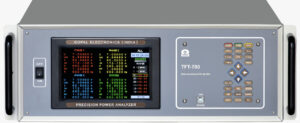
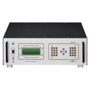
Stamping Watt Loss Tester
The Digital Single Sheet Tester is used to Measure the Watt Loss/Core Loss/ Iron Loss of CRGO/CRNO/CRC Steel Sheet or Stamping.
This method is used to get quick and tentative idea of watt loss of a single steel sheet.
Single Sheet Tester is suitable for a tentative evaluation of the sample, however for precision measurement users can go for Epstein Tester.
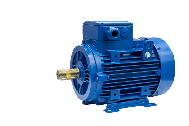
The no load test of 3 phase induction motor is performed on induction motor when it is running without load. This test tells us the magnitude of constant losses occurring in the motor.
The voltage applied for full load current is very small as compared to rated voltage. Hence, core loss due to small applied voltage can be neglected. Thus, the wattmeter reading can be taken as copper loss in the Motor.
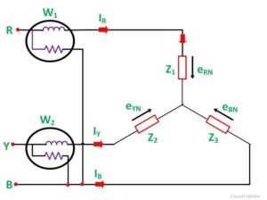
The two-wattmeter method is used to measure the input power of a three-phase induction motor.
The two wattmeter method is used in determining total power derived from the three phase load which is always constant, regardless of variations in phase power as well as angular displacement. Thus, the power output from a three-phase motor is also constant based on the findings using the said measurement.
The blocked rotor test enables us to determine the efficiency and the circuit parameters of the equivalent circuit of a 3-phase induction motor. In the blocked rotor test, the shaft of the motor is locked so that it cannot rotate and the rotor winding is short circuited.
In the blocked rotor test, the rotor is locked securely enough that it cannot break free. A low voltage is applied on the stator terminals so that there is full load current in the stator winding, and the current, voltage and power input are measured at that point.